Prior to 1973, we had a network known as “sneakernet”. To get files transferred between computers, you would typically have to save the file in some form of a disk or removable media and walk from one computer to another. Fortunately, in 1973, Xerox developed Ethernet.
Ethernet is a networking technology standard based on a bus topology. The Ethernet standard dominates most organizations’ local area networks (LANs). The original Ethernet standard used a single coaxial (coax) cable in a bus topology to connect several computers together.
The ends of the coax were terminated to prevent signal bounce. Ethernet wasn’t able to transfer data very quickly, at least not by today’s standards. However, it was a huge improvement over the sneakernet alternative.
It was not until about 1979 when Xerox partnered up with Digital Equipment Corporation (DEC) and Intel to publish and promote Ethernet. By this time Ethernet continued to run over coax cables at an improved speed of 10 megabits per second (Mbs).
Fortunately, Ethernet eventually became a standard adopted by the IEEE. The Ethernet standard (802.3) continues to be maintained by the IEEE. Ethernet implemented at the time was 10Base2 (thin Ethernet) and/or 10Base5 (thick Ethernet).
It is important to know that the designers of Ethernet had some challenges to resolve early on, such as how to send data across the network, how to identify the sending and receiving computers, and how to determine which computer should use the shared cable at what time.
These concerns were addressed by developing the concept of an Ethernet frame to encapsulate data, using hard-coded MAC addresses to identify hosts on the network, and developing a process called Carrier Sense Multiple Access with Collision Detection (CSMA/CD). These three items will be discussed in more detail in this article and upcoming ones in this series.
Ethernet in the 90’s
In the mid-1990s, Ethernet was being implemented on networks at an increased rate. The technology used to connect the nodes on the network began to improve as well. Rather than using a single coax cable to connect computers together, unshielded twisted pair (UTP) cabling was now being used. The IEEE 802.3 committee published this new version of Ethernet called 10BaseT which used hubs and UTP cabling.
Networks began seeing a change in the physical topology (layout). The older bus topology was being replaced by a new star topology. The change was slow at first. The backbone of networks continued as a bus (10Base5), but rather than plugging in computers on the bus, hubs were connected. Then from the hubs, you had several computers connected that fed into these new devices. It was now a lot easier to add computers to the network.
Now that hubs were starting to become widely available, it was much easier to implement Ethernet nodes on the network. 10Base2 network cabling was more difficult to work with when compared to UTP cabling. 10Base2 coax is very similar to the type of cabling you use in your home for connecting video devices, such as those the “cable company” would provide you with for your television sets.
UTP cabling is more like the cable you use to connect your phone lines. As a matter of fact, UTP Category 5 cabling is what is generally being installed for phone lines today, rather than the older Category 1 lines used a few decades ago.
Ethernet Frames
The concept of a frame is found at layer 2 of the OSI model. Network hosts will transmit frames, rather than all of the data at once, for two very good reasons. First, a network host that transmits the data in one big chunk will run the risk of something going wrong in the transmission.
For example, if you have a need to transmit 1 GB worth of data over the network and you sent the data over at one time and just before the data transmission completed an error occurred, that would require that the computer sending the data over the network start again from the beginning.
However, when data is managed in smaller frames, if a frame is damaged, the source computer can restart the communication at the point of the last frame that was received from the target computer. In addition, when multiple computers have access to the network at the same time, sending smaller frames allows more than one computer to participate in the network without having to wait until a computer completely sends all of the data to the target system.
Frame Structure
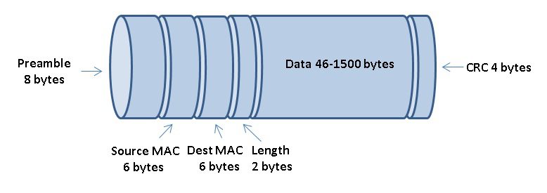
An Ethernet frame is made up of several important sections. The Ethernet frame contains more than just a chunk of data. It requires a preamble so that the nodes on the network can determine when a frame starts. In addition, a frame will contain source and destination MAC addressing so that the target system can know when a frame should be picked up by its Ethernet Network Interface Card (NIC).
After the addressing information, the frame includes information about its length. An Ethernet frame may carry up to a maximum of 1500 bytes of data in a frame. Next, you will find the data section of the frame. If both nodes are running TCP/IP, you will find higher-level protocol information included such as source and destination IP addresses.
If the Ethernet frame is less than 64 bytes in size, which is the minimum allowed, extra padding will be added to the data section. Finally, Ethernet frames have a cyclic redundancy check (CRC) section. The information stored in the CRC is used by the target system to determine if the frame is intact or was damaged during the transmission on the network.
CSMA/CD
Ethernet networks use a system called Carrier Sense Multiple Access with Collision Detection, or CSMA/CD for short. CSMA/CD is used by hosts on the network to determine when a network node can access the shared network cable at any given moment. Carrier Sense means that each node using the network examines the cable before sending a data frame.
In other words, the Ethernet node must first listen on the network to figure out if any other node is in the process of transmitting data. If the node determines that another node is transmitted, the node will wait a few milliseconds, then try again.
If no node is detected as transmitting, the node will attempt to access the network cable. Multiple access simply means that all nodes have equal access to the wire. If the line is free, any Ethernet node may begin sending a frame.
So what happens if two machines are both listening to the cable, and simultaneously decide that it is free and try to send a frame? Well, a collision will occur. The transmission from both nodes that accessed the network at the same time will be discarded. No other node on the network would be able to process the information from either node.
Keep in mind that when data is placed on the network, in reality, an electrical signal is what is sent on the wire. If another host interrupts that signal, the signal (data) from the originating host will be damaged. If a collision does occur, the nodes that were affected by the collision will delay their re-attempt to access the network.
Each with a random offset of time to mitigate the chance of another collision between the two nodes. It is easy for NICs to realize that a collision occurred. Collisions create unexpected voltages on the wire. Collisions are a normal part of the operation of an Ethernet network. On a typical half-duplex Ethernet network, you should expect to see about 10% of the frames collide.